

Monitoring Salinity in an Aquarium Can Be a Challenge
The biggest challenge when using a conductivity probe is getting a consistent reading. Many times, the reading is fouled by micro bubbles or debris getting into the probe.
The SPS Kit Solves this Problem

Getting Started
Installing the SPS Kit to your Conductivity Probe.
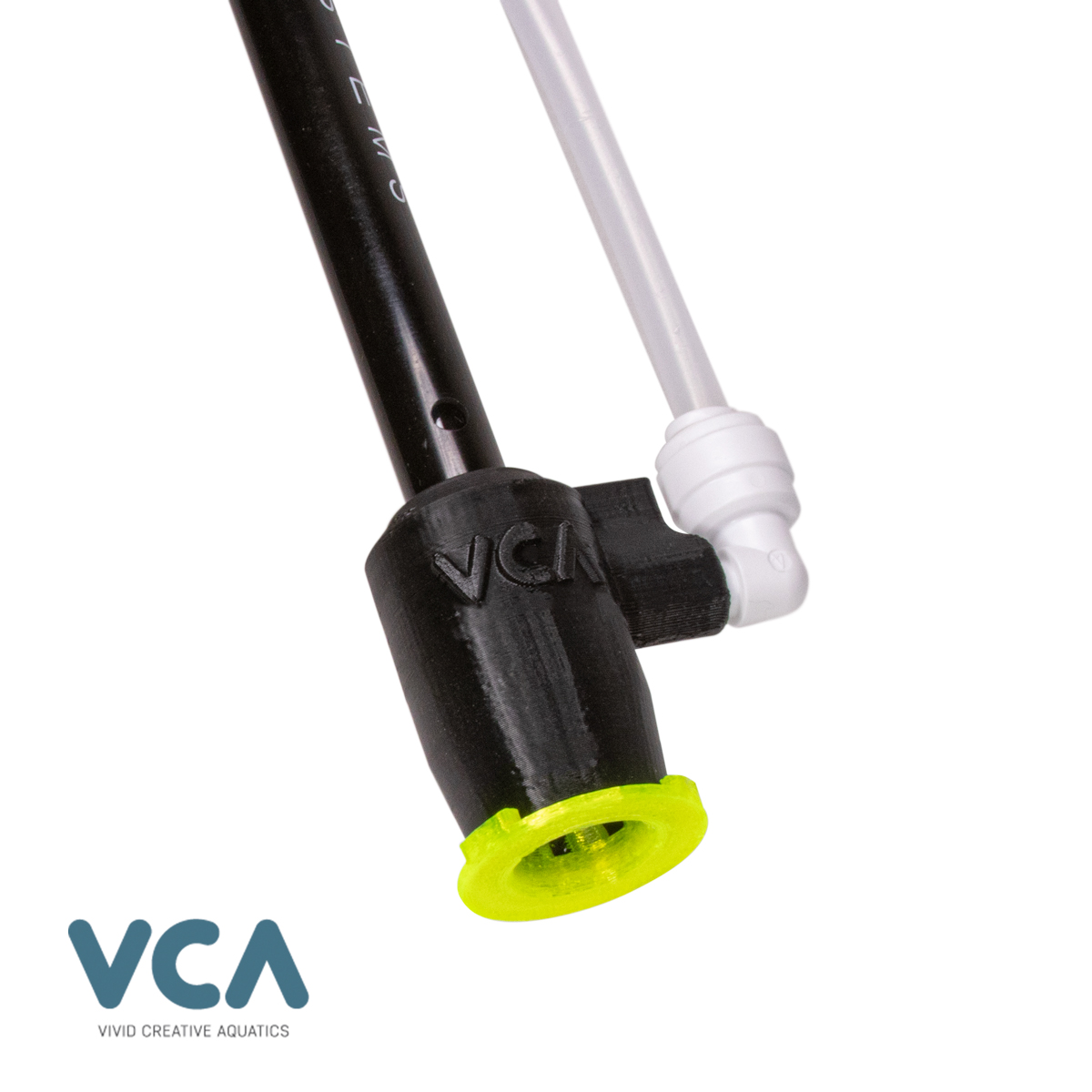
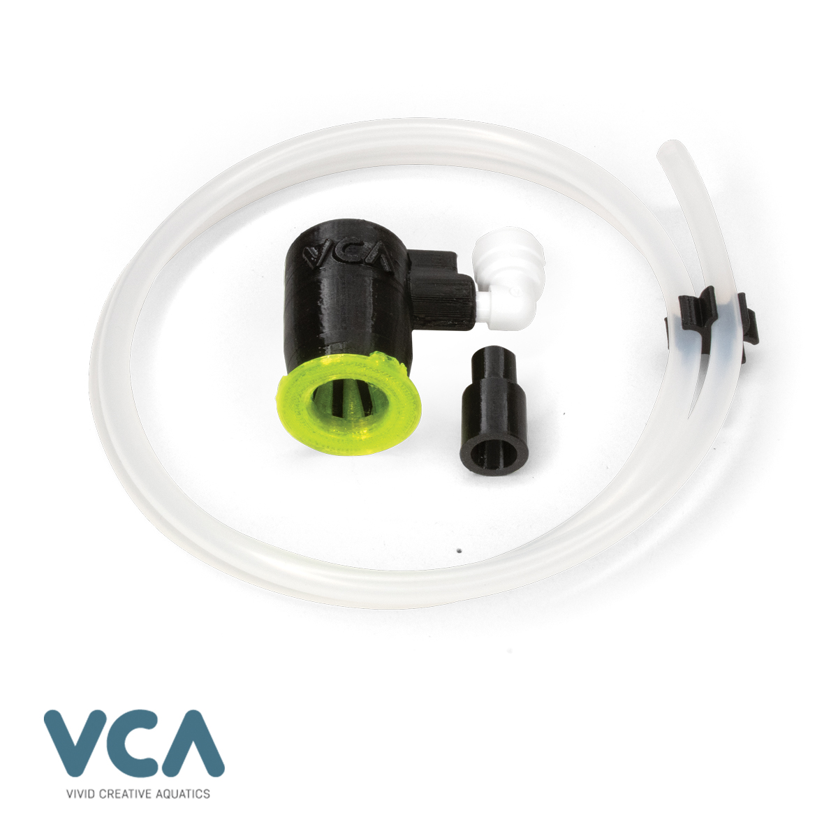
SPS Kit Assembly Overview
The SPS Kit is design to fit over the end to the conductivity probe. Installation should take just a few minutes. Both the probe and the Pressure Screen are delicate and care should be taken when assembling these two parts.
A) SPS SHIELD HOUSING
B) SPS PRESSURE SCREEN
C) STEM SPACER
D) QUICK-CONNECT FITTING
E) 1/4″ SUPPLY LINE
F) CONDUCTIVITY PROBE (Not Included)

Step 1.
Assemble Pressure Screen
Before inserting the Conductivity Probe, you must insure the Pressure Screen (B) is properly installed to the SPS Kit Housing (A)
Insert the pressure screen into the bottom of the housing. With firm pressure turn the Pressure Screen approximate 1/8th turn. This will lock on to the bottom of the housing.


Step 2.
Inserting the Conductivity Probe
The SPS Kit housing (A) is designed to fit over the end of the Neptune Systems Conductivity probe. However, the SPS Kit will work with any brand Conductivity probe with a similar electrode design and an outer diameter of 12mm.
WARNING: Both the Probe (F) and the Pressure Screen (B) are delicate. Care should be taken assembling the probe to the SPS housing.
TIP: It can be helpful to first wet the SPS Housing by dipping it in the tank water. This will help the probe smoothly slide into the housing with less resistance from the silicone o-ring inside.
While supporting the Pressure Screen (B), carefully insert the end of the probe (F) through the top of the SPS Shield Housing (A).
Ease the probe into the housing with a gently twisting motion.
Push the probe in until it stops against the Pressure Screen, inside the SPS Housing. Be careful not to damage the Pressure Screen.
Step 3.
Connect the Supply Line
You SPS Kit includes approximately 34in (86cm) of 1/4in tubing. The tube should be connected to the Quick-Connect fitting (D) while the other end will be connected to a flow source.
The tube is used to supply the SPS Kit with the necessary flow. You may shorten the tube if needed. If you do shorten the tube, it is recommended you keep the length of the tube at least 12 to 14 in (30 to 35 cm) in length.
Tip: You may rotate the Quick-Connect fitting to best accommodate the supply line.

Step 4.
Connect the SPS Kit to a Flow Source
The SPS Kit needs a consistent and steady supply flow to produce the most reliable readings. For best results, a steady flow rate of between 20 and 60 GPH (75 to 225 LPH) is required.
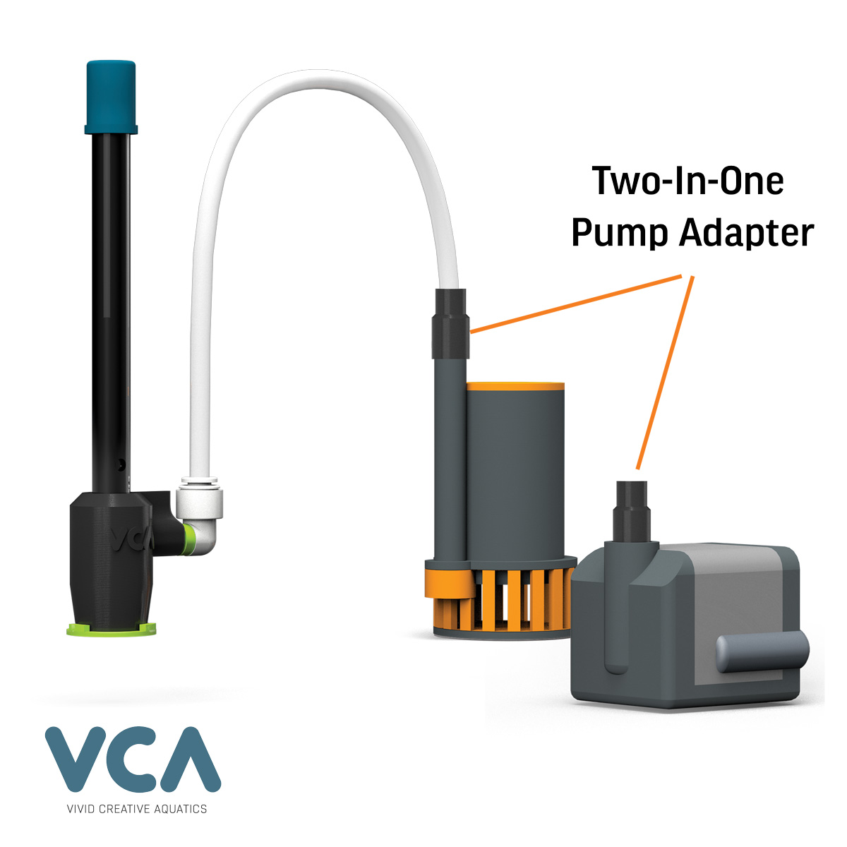
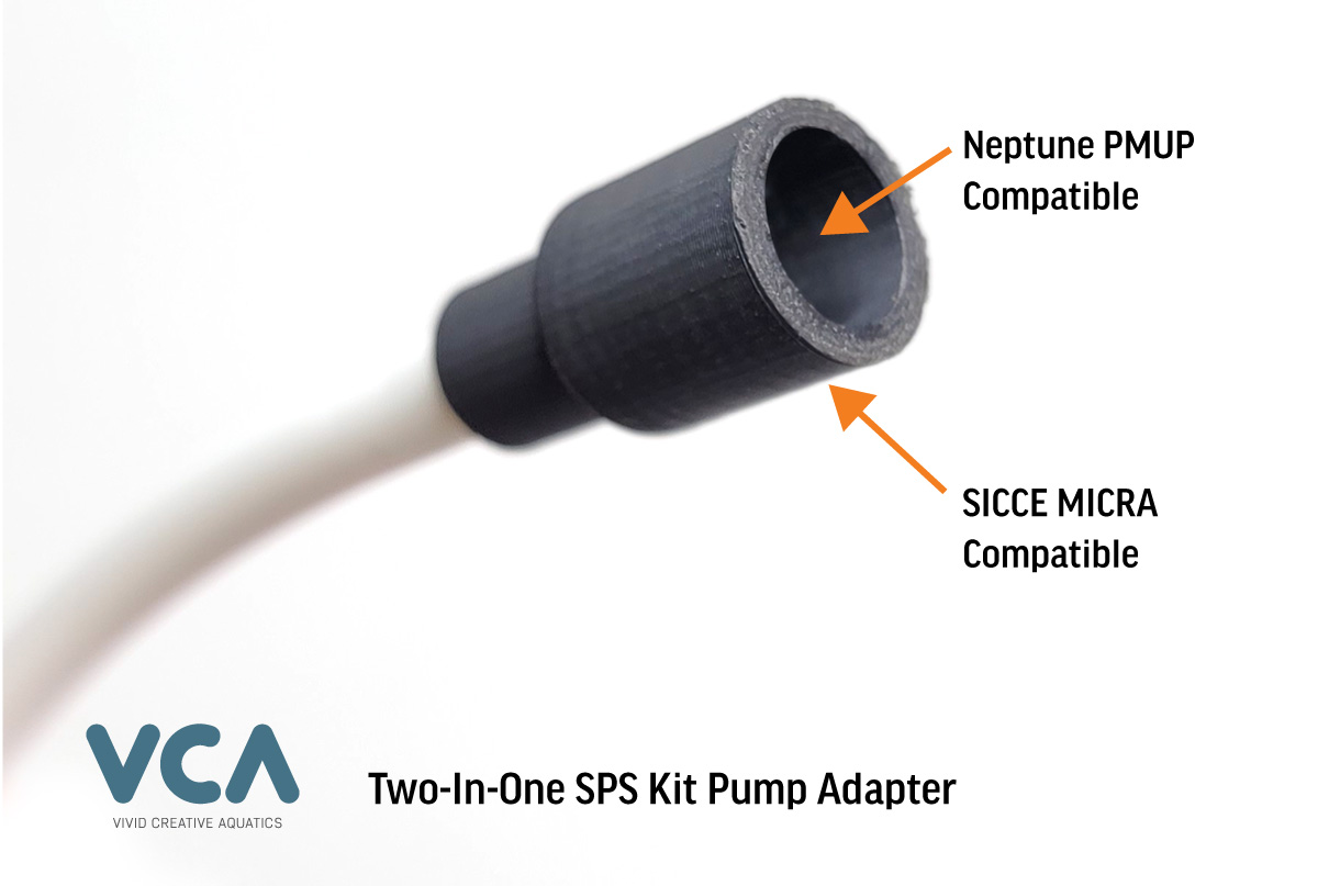
To achieve the proper flow rate, we recommend a feed pump rated for 60 to 90 GPH (227 to 340 LPH). Two such pumps are the Neptune PMUP and the SICCE® Micra.
The SPS Kit includes a 2-in-1 adapter that fits both the Neptune PMUP and the SICCIE® Micra (90GPH version).
You may also connect the supply line to an open port on a return line plumbing manifold.
IMPORTANT: Higher flow rates will result in a higher salinity readings. it is recommended that you do not supply more than 90 GPH (340 LPH) to the SPS Kit.
The Initial Setup
Setting up your Conductiviy Probe with the SPS Kit.

Turn on TC Factor
It is highly recommenced you turn on Temperature Compensation (TC) in the APEX Fusion Dashboard under the Conductivity Probe Configuration page.
First Things Fist
Salinity readings are affected by temperature. As the temperature in your aquarium drops, your salinity rises. In tern, as the temperature rises, your salinity will drop.
Because the SPS Kit will help your probe provide a more reliable and steady reading, the effects of variation in salinity caused by temperature will be very evident.
For this reason, it is recommended that you activate Temperature Compensation (TC ) in the APEX Fusion dashboard. A typical TC factor for saltwater aquarium is 2.2.
This will help create a more stable and reliable reading and minimize the daily swings that can be caused by water temperature rising and falling.
Step 1.
Turn On The Flow!
Place the Conductivity Probe with the SPS Kit installed into your aquarium. Then turn on the feed pump.
You should expect to see the SPS Kit expel bubbles as the flow is turned on.
Tip: It works best if you submerge the probe with the SPS Kit installed BEFORE turning on the flow. This creates the necessary pressure to expel the trapped air.


Step 2.
Give it a Gentle Shake
Next, gently shake the probe up and down. This will help to dislodge any bubbles that may still be trapped inside the housing.
Step 3.
Final Step
Cover the opening at the bottom of the SPS Kit with your finger for a few seconds. This will expel any remaining bubbles and insure their are no air pockets around the tip of the probe.
Mount he probe in your desired location. At this point, do not expose the tip of the probe to air. If you do need to lift the probe out of th ewater, you will need to repeat steaps 2 and 3.


Step 4.
Wait For Readings to Settle In
You should expect a settle-in period of few minutes to as much as an hour. Once settled in, your salinity reading will level out and you should begin to see a steady trend line.
Tip: After two hours, if the reading has not settle, you can repeat steps 2 and 3.
Frequently Asked Questions
what to expect, calibration and trouble shooting
My reading with the SPS Kit installed is not the same as my actual salinity.
The SPS Kit will not necessarily make your probe read a more accurate number. Instead, the SPS kit will work to make the trend line more reliable. A typical reading from a Conductivity probe with the SPS kit properly installed, can be between 28 and 38.
If you know the salinity level in your aquarium is 35 PPM, then the actual number the conductivity probe is reading is less important than knowing if the salinity level is trending up or if salinity level is trending downwards.
For example, if your Auto Top Off system is stuck on and freshwater is being added into your sump, then the Salinity may drop, and a reliable and constant reading would make that trend line easy to spot.
My Reading is too low or continues to drop (Below 28 and/or Dropping)
A reading that is too low or continues to drop below 28, usually is caused by bubbles or air inside the SPS kit housing.
Bubbles entering the housing through the opening at the bottom can sometimes be caused due to not enough flow to the SPS kit.
Bubbles can also make their way into the housing if the supply flow has excessive air or bubble in it.
For instance, if you use the Bubble Scrubbing technique in your aquarium, and the feed pump or the supply line from a manifold port is drawing in the microbubbles during scrubbing session, it can cause a build up of air inside the housing. In this case, SPS kit will generally recover after a few minutes to an hour once bubble scrubbing is stopped.
My Reading is too high (45 to 50+)
A consistent high reading while using the SPS kit is generally is caused by too much flow going through the SPS kit body. This can sometimes be caused by a supply line that is too short (les then 14 in) or a pump that is over supplying the SPS Kit. Try reducing the flow to the SPS kit.
Its important to note, that a High reading can sometimes be caused by supply flow being cut off to the SPS housing for prolonged periods of time.
The Pressure Screen is broken during installation.
The pressure screen is a very delicate piece and care should be taken when assembling the probe into the SPS kit housing. If your kid arrives with a broken screen, please reach out to support and we will finally replace that screen for you. We also offer replacement screens directly from our website.
It is important to note, that the SPS kit can work without the Pressure Screen in place. The biggest challenge will have running an SPS kit without the pressure screen is ensuring that the tip of the probe is properly positioned inside the SPS body housing. The pressure screen makes it easy to position the tip in the right position, but it is possible to do this without the screen. Please see the below diagram.